Introduction to GD&T

During WW II companies had to “farm out” parts because of the quantities/schedules. This meant the new manufacturer had to interpret the drawing hence the “centerlines” were often established by contacting features that were not functional or important and features produced from these incorrect “centerlines” were not at the location required.
The parts did not assemble and/or did not function properly hence had to be fixed or scrapped. GD&T was the solution to this major problem. GD&T provides a designer the tools to have clear, concise, and consistent instructions as to what is required.
It eliminates ambiguities hence everyone that is involved with the part will not have to interpret the dimensioning.
What is GD&T?
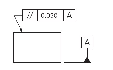
It is compilation of symbols and rules that efficiently describe and control dimensioning & tolerancing for all drawings (castings, machined components,etc.). It is documented in ASME Y14.5M which has the symbols, rules, and simple examples. Also ASME Y14.8 has guidance for casting and forging drawings.
Why we use GD&T?
a. It is a simple and efficient method for describing the tolerancing mandated by the designer of the part.
b. It eliminates ambiguities as to what Datum features are to be contacted to establish the Datum planes and Datum axis that are to be used for locating other features. All inspection will result in the same result – the dimension is within or out of tolerance.
c. It simplifies inspection because hard gages can often be utilized and inspection fixtures are often mandated which simplifies inspection for production quantities.
d. It forces the designer to totally consider function, manufacturing process, and inspection methods. The result is larger tolerances that guarantee function, but reduce manufacturing & inspection costs. Also the “bonus” or extra tolerance for certain conditions can result in significant production cost savings. In addition the time to analyze whether a missed dimension is acceptable is dramatically reduced


